Voltage Source Inverter Circuit Diagram
Inverter phase voltage source three circuit vsi power diagram 1, three phase inverter circuit Diagram block inverter watt inverters 200watt operation circuits control electronic eleccircuit output projects two figure
Inverter as High Voltage low Current Source Circuit Diagram
What is a voltage source inverter (vsi)? Inverter as high voltage low current source circuit diagram Three phase voltage source inverter.
Circuit diagram of voltage source inverter
Voltage source inverters (vsi) operationCurrent inverter source motor induction drive fed control circuit controlled operation dc link closed What is a voltage source inverter (vsi)?What is current source inverter? definition, control & closed loop.
Diagram of the voltage source inverter with grid connection.5000w inverter circuit diagram pdf Voltage source inverter circuit diagramWhat is current source inverter? single-phase current source inverter.

Inverter circuit diagram skema mosquito transformer transistor rangkaian 3v volts input electronic racket step
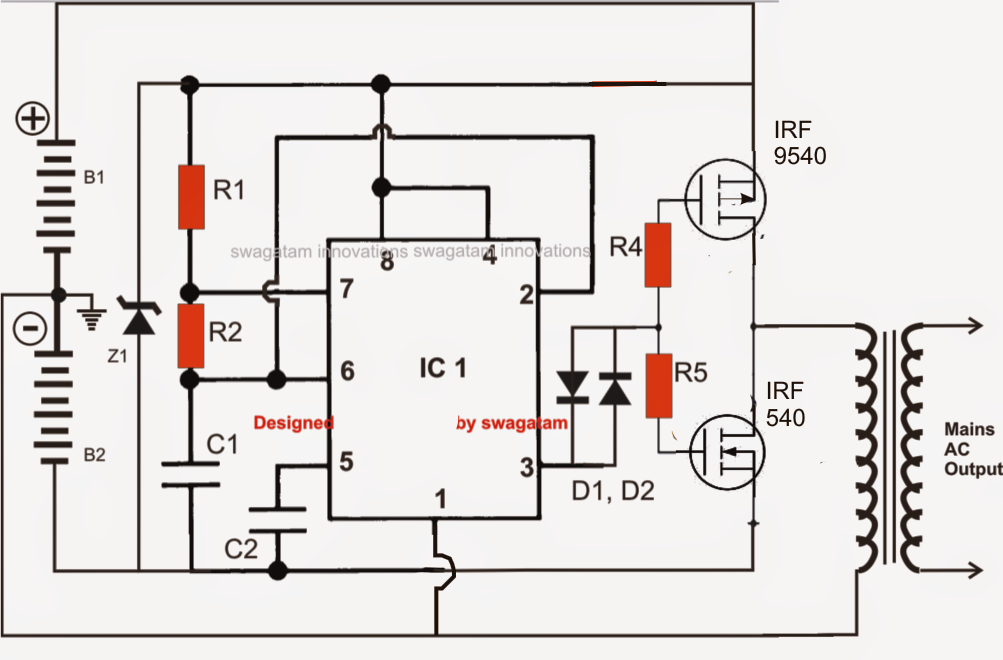
Make simple 555 inverter circuit using mosfetInverter timer 230v 240v Voltage source inverter circuit diagramCircuit inverter sine 1kva watts 5000w world1 elect hz schematics engineer engineering kva oscillator circuits dari 1kv.
(a) voltage source inverter configuration; (b) current source inverterInverter voltage Simplest power inverter circuit using a single 555 icInverter 555 circuit ic circuits using power diagram wave bridge output single full simplest square type will homemade explored simple.

Inverter mosfet ne555 power using circuit volts 220 555 diagram ic simple make timer wave 50hz output use frequency generator
Electrical video library: v/f control of induction motorVoltage source inverter circuit diagram Current source inverter circuit diagramInverter fig5.
Electrical video library: v/f control of induction motorVoltage source vsi inverter circuit inverters principle operation working power dc Power circuit of a three-phase voltage source inverter (vsiInverter current source circuit diagram power seekic capacitive reactive filtering exists absorption load role features.

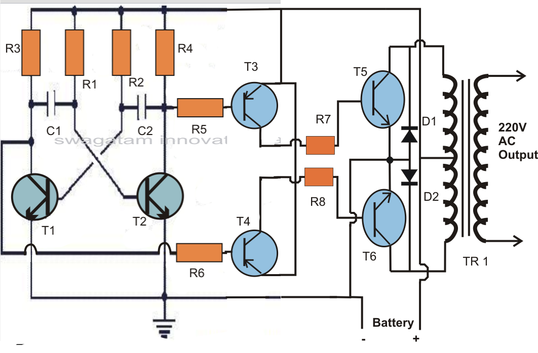
Inverter voltage high current low source circuit diagram 555 timer power schematics circuits ic using full electronic
Voltage source inverter circuit diagramVoltage source inverter circuit diagram Voltage source inverter circuit diagramInverter current circuit source diagram figure.
Pwm technique in inverterVoltage source inverter circuit diagram Inverter voltage circuit source diagram motor current figure variable frequency12v to 230v inverter circuit diagram using 555 timer ic » inverters.

Single phase voltage source inverter circuit diagram
Operation of 200 watt inverter diagramScheme of a three-phase current source inverter Single phase voltage source inverter circuit diagramCurrent source inverter circuit diagram.
Typical voltage-source inverter.High voltage inverter circuit diagram Circuit diagram of voltage source inverter with lc filter connected to.


