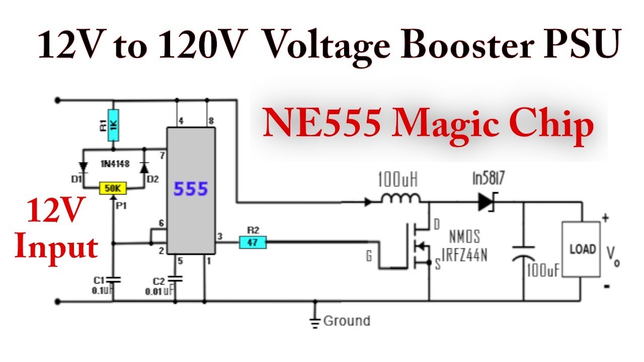
555 Timer Boost Converter Circuit Diagram
Timer 555 circuit diagram schematic ne555 datasheet pinout discrete kit does block circuits transistor works eleccircuit integrated functional pins connection Converter 5v 15v circuit lm2577 7v diagram 12v regulator datasheet Converter 555 120v 12v
How does NE555 timer circuit works | Datasheet | Pinout | ElecCircuit.com
555 timer circuits diagram 555 timer boost converter circuit diagram Timer pinout block modes من الجهد
555 timer as oscillator
Boost converter circuit 555Introduction to the 555 timer Timer circuits555 timer converter ic ne555 circuits how2electronics 35v.
How does ne555 timer circuit worksBoost converter circuit 555 555 timer diagram chip ic block transistor tutorial discharge multivibrator does circuit logic electronics flop flip monostable bistable mode projectsSimple dc-dc converter using 555 timer ic (7.5-35v).

555 boost converter circuit ic components timer using transistor bc547 capacitor npn required theorycircuit
555 timer boost converter (and buck converter) switching powerDc to dc boost converter circuit using 555 timer Calculated mosfet switching time does not agree w/ expected results555 timer circuit diagram tutorial.
12+ 555 timer ic pin diagram555 timer tutorial Ne555 timer pin diagramDc to dc boost converter using 555 timer ic (6 to 24).

7 ideas of 555 dc boost converter circuit (with images)
Dc to dc boost converter using 555 timer archivesBoost converter circuit timer flasher led ic configuration ne555 theorycircuit High voltage boost converter circuitBoost converter circuit using ic 555 – diy electronics projects.
Dc converter 555 circuit boost timer ne555 gnd ic using diagram pcb circuits eleccircuit step supply voltage board output 5vDc to dc boost converter circuit using 555 (tutorial : Lm2577 boost converter circuitA simple dc-dc boost converter circuit using 555 timer ic.

Dc converter circuit 555 simple ic isolated using boost digital diagram transformer circuits output power timer eleccircuit transistor current works
555 timer icConverter 555 boost timer switching power mosfet schematic supply mode pcb time circuit dc regulator nixie switch spec meet projects 555 timer oscillator diagram internal integratedIc 555 circuit diagram.
555 timer boost converter circuit diagram555 timer ic schematic diagram How does a 555 timer work?Isolated dc converter for digital using 555.

555 circuitbasics astable multivibrator
Boost converter 555 timer using ic simple figure schematic capacitor banks chargingBoost converter circuit using ic 555 – diy electronics projects 555 timer icBoost bucker converter circuit diagram.
555 converter buck boost timer regulator power eevblog forum switchingBoost converter circuit using ic ic555 electronics Figure 2 from simple boost converter using timer ic 555 for chargingBoost converter circuit using 555 timer ic.

Dc converter boost circuit 555 using tutorial kaynak
555 dc-dc boost converter power supply .
.


